Search Results
 Radiography With Richie
Designed to empower emerging imaging professionals with the absolute safest, clearest, and most confident path to mastering basic diagnostic X‑rays in clinical settings.
Our goal is simple: to provide the safest, easiest, and least intimidating path to learning X‑ray positioning and terminology.
This educational resource is designed for the modern clinical professional tasked with delivering high-quality diagnostic imaging in a fast-paced environment. Whether you are providing support in an outpatient setting, an urgent care clinic, or are in the early stages of your medical imaging journey, this platform offers a practical, clear, and stress-free approach to mastering radiographic fundamentals. If your clinical responsibilities include patient x-ray positioning, equipment alignment, or producing diagnostic views under medical supervision, these guides were built to help you perform your role with total confidence and a safety-first mindset.
This site focuses on foundational, practical knowledge, including:
- Basic X‑ray terminology
- Patient x-ray positioning explained in plain language
- Central ray (CR) placement and SID guidance
- Common x-ray positioning mistakes and how to avoid them
- Safety‑first imaging principles
Each imaging position is broken down into clear, repeatable steps so learners understand what to do and why it works.
Many educational resources assume prior x-ray positioning experience or use complex technical language. This site does not. What sets this project apart:
- ✅ Designed for clinical clarity and immediate application
- ✅ No physics overload or unnecessary jargon
- ✅ Step‑by‑step instructions that build confidence
- ✅ Focused on patient safety and image quality
- ✅ Structured like a hands‑on training guide, not a textbook
Learning X‑ray positioning should not be overwhelming — and here, it isn’t.
This site is educational in nature. It does not replace formal radiology education, regulatory requirements, or employer policies.
All instruction emphasizes:
- Radiation safety principles
- Proper patient communication
- Limiting repeats through correct x-ray positioning
- Performing imaging only within the scope permitted by local and facility policy
- Start with the Radiology Training section
- Review x-ray positioning by body region
- Practice concepts alongside supervised clinical imaging
- Return as a reference when needed
The site is designed to be:
- Used during orientation
- Referenced during training
- Accessed quickly in a clinical environment
This site was developed by a radiology professional with extensive experience in clinical imaging and staff training, with a focus on bridging the gap between theory and the clinical floor.
Ready to Begin X-Ray Positioning?
Start with the X-Ray Positioning Guide section and click the Terminology Hub if a term is unfamiliar. Begin learning X‑ray positioning the right way — safely, clearly, and without intimidation!
Clinical X-Ray Positioning Guides
How to Use This Guide: Click any anatomical category below to open the menu, then select your specific view. Use the Setup bullet points on the left for instant baseline protocols (Centering, Position, and Technical factors), and click the Reference Image on the right to open a full-screen x-ray positioning visual.
- Position: Rest forehead and nose against the board so the OML orbitomeatal line (corner of eye to center of the ear) is perfectly perpendicular to the IR.
- Centering: Angle the tube 15° caudad (toward the feet) to exit at the Nasion, the top part of nose at the inner corners of the eyes.
- Collimation: Crop the light to closely frame the outer borders of the skull skull.
- Exposure: Use 72 kVp @ 32 mAs as a baseline setting.
- Tube Setup: Set a 40-inch SID with a 15° downward (caudad) angle.

- Position: Rest the chin on the center of the bucky (IR) and tilt the head back so the orbitomeatal line OML (eye-to-ear line) is at a 37° angle.
- Centering: Aim the central ray at the back of the patient's head to exit at the acanthion (the groove right at the base of the nose, above the upper lip).
- Collimation: Crop the light to frame the facial bones, including the full skull margin from the top of the head and bottom of the chin, and ear to ear.
- Exposure: Use 70-80 kVp with a Grid to clearly display the air-filled sinus cavities.
- Tube Setup: Set a 40-inch SID (tube distance) with a 0° straight beam (no angle).

- Position: Tuck the chin to bring the OML orbitomeatal line perfectly perpendicular to the IR.
- Centering: Aim the central beam to enter 2.5 inches above the between the eyebrows at the glabella (near the hairline) and exit the foramen magnum, where the cervical spine articulates with the base of the skull.
- Collimation: Crop the light to closely frame the outer margins of the skull.
- Exposure: Use 75-85 kVp with a Grid to punch through the thick occipital bone.
- Tube Setup: Set a 40-inch SID. Angle the tube 30° downward (caudad) to the orbitomeatal line OML.

- Position: Rest forehead and nose against the board so the orbitomeatal line OML (eye-to-ear line) is perfectly perpendicular to the bucky (IR) .
- Centering: Aim the central ray crosshairs to exit at the glabella (the smooth flat area between the eyebrows).
- Collimation: Crop the light square to closely frame the outer edges of the entire head and jaw.
- Exposure: Use 70-80 kVp with a Grid to punch through the thick bone safely and clearly.
- Tube Setup: Set a 40-inch SID (tube distance) with a 0° straight beam (no angle).

- Position: Turn the head completely sideways against the board so the IPL (pupil-to-pupil line) is straight up and down.
- Centering: Aim the beam 2 inches above the EAM (the ear hole opening).
- Collimation: Open the light to cover the entire front, back, and top rounded edges of the skull.
- Exposure: Use 75-85 kVp with a Grid to push through the dense sides of the brain case.
- Tube Setup: Set a 40-inch SID (tube distance) with a 0° straight beam (no angle).

- Position: Rest the affected side of the face against the board so the IPL (pupil-to-pupil line) is perfectly perpendicular to the bucky (IR).
- Centering: Aim the central ray crosshairs directly at the cheek bone zygoma, halfway between eye and ear).
- Collimation: Crop the light to include the front of the face to the ear so the temporomandibular joint is included. Also include the forehead halfway to the hairline, and lower jawline.
- Exposure: Use 65-75 kVp, dropping the power slightly since facial bones are thinner than the skull.
- Tube Setup: Set a 40-inch SID (tube distance) with a 0° straight beam (no angle).

- Views Required: Waters View, Right Lateral, and Left Lateral.
- Why Both Laterals? Nasal bones are thin and superimpose easily. Taking both right and left profiles ensures a unilateral fracture isn't hidden by the opposite side, and it provides an uninjured side for comparison.

- Position: Stand facing the board, rolling shoulders forward to move shoulder blades off the lungs.
- Centering: Aim the central beam at T7 (align with the bottom tips of the shoulder blades).
- Collimation: Open the light to frame from just above the shoulders to the lower rib cage.
- Exposure: Use 110-120 kVp to penetrate the heart and visualize delicate lung tissue clearly.
- Tube Setup: Set a 72-inch SID (tube distance) with a 0° straight beam (no angle).
- Breathing: Instruct the patient to "Take in a deep breath. Blow it all the way out. Take in another deep breath and hold it."

- Position: Stand with the left side flat against the board, raising both arms high above the head.
- Centering: Aim the beam at T7, entering the mid-coronal plane (directly beneath the armpit).
- Collimation: Crop the light to include the front of the chest to the back edge of the spine.
- Exposure: Use 110-120 kVp, increasing mAs slightly to punch through the thicker side profile.
- Tube Setup: Set a 72-inch SID (tube distance) with a 0° straight beam (no angle).
- Breathing: Instruct the patient to "Take in a deep breath. Blow it all the way out. Take in another deep breath and hold it."

- Position: Lie flat on the back with arms comfortably out of the way of the stomach area.
- Centering: Aim the central beam directly at the iliac crests (the top curves of the hip bones).
- Collimation: Open the light to cover the upper abdomen entirely down to the pubic bone.
- Exposure: Use 75-85 kVp with a Grid to cleanly penetrate the dense abdominal soft tissues.
- Tube Setup: Set a 40-inch SID (tube distance) with a 0° straight beam (no angle).
- Breathing: Instruct the patient to "Take in a deep breath. Blow it all the way out. Hold it out there."

- Position: Stand straight with the back flat against the board, distributing weight evenly.
- Centering: Aim the beam 2 inches above the iliac crests to ensure the diaphragm is included.
- Collimation: Crop the light to frame the upper abdomen, ensuring you catch any free air under the lungs.
- Exposure: Use 75-85 kVp with a Grid to clearly visualize bowel gas patterns and soft tissue.
- Tube Setup: Set a 40-inch SID (tube distance) with a 0° straight beam (no angle).
- Breathing: Instruct the patient to "Take in a deep breath. Blow it all the way out. Hold it out there."

- Position: For a posterior Rib injury (Patient's back):Stand the patient with their back against the bucky or have them lie supine on the table (on their back). If the patient has an anterior rib injury (Patient's Chest), stand the patient with their chest against the bucky(IR) or prone on the table (on their stomach).The injured or affected side should be closer to the IR (Bucky).
- Centering (Upper Ribs): Aim the central beam at the center of the chest/back on the patients affected side (injured side). Level of T7, about 3-4 inches below the jugular notch.
- Centering (Lower Ribs): Lower the x-ray tube so the the central ray (CR) crosshairs are halfway between the lower tip of the breastbone (xiphoid process) and the bottom edge of the flank ribs. Be sure to include the very lower border of the upper Ribs x-ray on the this lower Ribs x-ray image so no anatomy is missed or left out.
- Exposure: Use 70-75 kVp for upper ribs to catch bone detail over the air-filled lungs; use 75-85 kVp with a Grid for lower ribs to punch through thick abdomen tissues.
- Tube Setup: Set a 40-inch SID (tube distance) with a 0° straight beam (no angle).
- Breathing (Upper Ribs): "Take a deep breath IN and hold it." (Pushes the diaphragm down out of the way).
- Breathing (Lower Ribs): "Blow your breath OUT and hold it." (Lets the diaphragm rise up out of the way).

- Position: For a posterior or back Ribs injury, have the patient stand with their back against the bucky or lie them supine on their back on the table (IR). Rotate the patient's non-injured side 45° away from the bucky (IR). If the patient has an anterior Ribs injury, have the patient positioned with their chest against the IR (bucky) or lie them prone on their belly on the table. Rotate the patient's non-injured side 45° away from the bucky (IR) The injured side will always be the side touching the IR (Bucky). Pro-Tip: If the patient has an anterior injury (chest), do PA Oblique Ribs X-ray positioning. If the patient has a posterior injury do AP Oblique Ribs X-ray positioning.
- Centering: Aim the beam halfway between the spine and the Lateral (outer side) of the patient chest/back on the affected side (injured side).
- Exposure: Use 70-80 kVp with a Grid to account for the rotated thickness of the body profile.
- Tube Setup: Set a 40-inch SID (tube distance) with a 0° straight beam (no angle).
- Breathing: Take a deep breath IN and hold it." (Pushes the diaphragm down out of the way).

- Position: Stand or lie flat, lifting the chin slightly to line up the upper teeth with the base of the skull.
- Centering: The central ray is angled 15-20 degrees cephalad, toward the head, at C4 (Adam's Apple). Generally, this will be halfway between the sternal notch and the tip of the slightly elevated chin.
- Collimation: Crop the light to include the base of the skull down to the top of the shoulders. Pro Tip: The light field should include the top of the ears and the sternal notch.
- Exposure: Use 70-80 kVp to see the delicate cervical vertebrae structures clearly through the soft tissue.
- Tube Setup: Set a 40-inch SID with the tube angled 15° to 20° upward (cephalad).

- Position: Have the patient open their mouth wide and align the lower edge of the upper teeth to the mastoid tips (lowest part of the back of the skull) perfectly perpendicular to the IR.
- Pro Tip: Politely ask the patient if they have any removeable dental work (False Teeth) that can be taken out. Dental work will obscure anatomy. Have them take out removeable dental work out prior to imaging
- Centering: Aim the central beam directly through the center of the open mouth. The laser crosshairs will form a plus sign from the tip of the patient's nose to the chin and the corners of their mouth.
- Collimation: Crop tightly to a 5x5 inch square catching only the lips and mouth opening. The bones you are imaging are only behind the jaw
- Exposure: Use 70-80 kVp to penetrate the teeth and base of the skull.
- Tube Setup: Set a 40-inch SID with a 0° straight beam (no angle).

- Position: Stand in a true lateral profile, dropping the shoulders down as far as possible to clear the lower neck. Have larger patients hold weighted bags in each hand to help lower thick shoulders.
- Centering: Aim the central ray perpendicular at C4 (Adam's apple).
- Collimation: Open the light to include the top of the ear down to the jugular notch.
- Exposure: Use 70-85 kVp to penetrate the lateral neck tissue clearly.
- Tube Setup: Set a 72-inch SID to reduce magnification, using a 0° straight beam.

- Position: Rotate the entire body 45° from an AP position to open the intervertebral foramina.
- Centering: The central ray is angled 15-20 degrees cephalad, toward the head, at C4 (Adam's Apple).
- Collimation: Crop the light to include the base of the skull to the top of the shoulders.
- Exposure: Use 70-80 kVp.
- Tube Setup: Set a 72-inch SID with the tube angled 15° to 20° upward (cephalad).

- Position: True lateral. Raise the arm closest to the IR (bucky) straight up and supported by lying over the top of the patients head for comfort and stability. By raising the arm and shoulder up, this position will drop the other shoulder lower to better visualize the C7-T1 junction.
- Centering: Aim the central ray perpendicular at C7-T1 (the prominent posterior bump at the base of the neck).
- Collimation: Crop the light to frame the lower neck and upper mid-chest.
- Exposure: Use 75-85 kVp to punch through the dense shoulder joint overlay.
- Tube Setup: Set a 40-inch SID. Use a 3° to 5° downward (caudad) angle if the shoulders cannot separate fully.

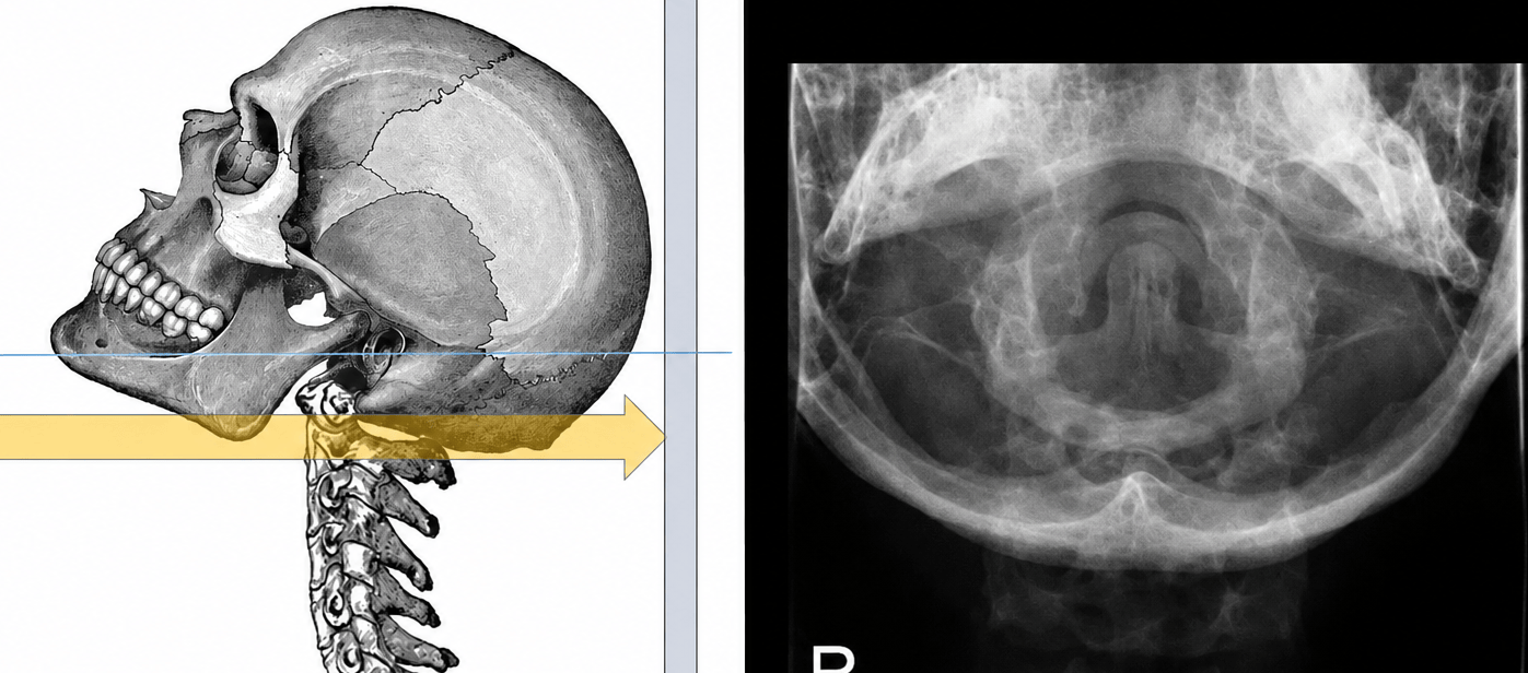
- Position: Supine or erect, elevate chin until tip of chin and mastoid tips are vertical.
- Centering: Central ray directed perpendicular to midpoint of mandible (inferior tip of chin).
- Collimation: Collimated to a 5x5 inch field centered over C1-C2 region.
- Exposure: 75–80 kVp, adjust mAs for dense bone visualization.
- Tube Setup: 40" (100 cm) SID, grid recommended.
- Position: Lie flat on the back (supine) and flex the knees to reduce the natural curve of the spine.
- Centering: Aim the central beam at T7 (align with the inferior angle of the scapulae).
- Collimation: Crop narrowly side-to-side, from the jugular notch down to the xiphoid process.
- Exposure: Use 80-90 kVp with a Grid to manage scatter from the chest cavity.
- Tube Setup: Set a 40-inch SID with a 0° straight beam (no angle).

- Position: Lie in a true lateral profile, flexing the knees for stability and bringing the arms straight forward.
- Centering: Aim the central beam at T7 (align with the inferior angle of the scapulae).
- Collimation: Crop to include the lower neck down to the lower ribs.
- Exposure: Use 80-90 kVp. Utilize a breathing technique (low mA, 2-3 second exposure) to blur the ribs out of the way.
- Tube Setup: Set a 40-inch SID with a 0° straight beam. Support the waist to keep the spine parallel to the table.

- Position: Lie flat on the back, flex the knees, and plant feet flat on the table to flatten the lower back against the IR. If the patient is unable to lie down due to pain or injury, position them standing with their back against the upright bucky (IR).
- Centering: Aim the central ray directly at the iliac crests (L4 level).
- Collimation: Open the light to frame from the lower ribs down to the mid-pelvis.
- Exposure: Use 80-90 kVp with a Grid to penetrate the dense abdominal structures cleanly.
- Tube Setup: Set a 40-inch SID with a 0° straight beam (no angle).

- Position: Lie in a true lateral profile with knees flexed. Place a sponge under the waist to keep the spine perfectly parallel to the table. If the patient is unable to lie down due to pain or injury, position them standing with their left side against the upright bucky (IR).
- Centering: Aim the central beam at the iliac crests (L4 level).
- Collimation: Crop to include the lower ribs down to the sacrum.
- Exposure: Use 85-95 kVp with a Grid, utilizing high power for the thickest part of the torso.
- Tube Setup: Set a 40-inch SID with a 0° straight beam. Angle 5° to 8° downward (caudad) only if the waist sags and cannot be supported.

- Position: Maintain the true lateral recumbent position used for the Lateral L-Spine view.
- Centering: Aim the beam 1.5 inches inferior to the iliac crest and 2 inches posterior to the ASIS (front hip bone).
- Collimation: Crop tightly to an 8x10 or 5x5 inch square focused directly on the lumbosacral joint.
- Exposure: Use 90-100 kVp with a Grid, increasing power to punch through the dense pelvis.
- Tube Setup: Set a 40-inch SID. Use a 5° to 8° downward (caudad) angle if the hips are wide and the spine sags.

- Position: Roll the body 45° from a supine position onto the right side to visualize the right-side zygapophyseal joints (Scottie Dogs). If the patient is unable to lie down due to pain or injury, position them standing in an AP oblique position at the upright bucky (IR). Their back to the bucky with their body turned on a 45 degree angle to the patient's right side.
- Centering: Aim the beam 1.5 inches above the iliac crest and 2 inches medial to the elevated (left) ASIS (L-3).
- Collimation: Open the light to frame from the lower ribs to the SI joints.
- Exposure: Use 80-90 kVp with a Grid.
- Tube Setup: Set a 40-inch SID with a 0° straight beam.

- Position: Roll the body 45° from a supine position onto the left side to visualize the left-side zygapophyseal joints (Scottie Dogs). If the patient is unable to lie down due to pain or injury, position them standing in an AP oblique position at the upright bucky (IR). Their back to the bucky with their body turned on a 45 degree angle to the patient's left side.
- Centering: Aim the beam 1.5 inches above the iliac crest and 2 inches medial to the elevated (right) ASIS.
- Collimation: Open the light to frame from the lower ribs to the SI joints.
- Exposure: Use 80-90 kVp with a Grid.
- Tube Setup: Set a 40-inch SID with a 0° straight beam.

- IR Size: 10x12 Lengthwise
- SID: 40 inches
- Patient Position: Supine, legs extended
- Central Ray (CR): Angled 15° cephalad (toward the head), entering 2 inches superior to the pubic symphysis (generally mid-pelvis).
- Respiration: Suspend respiration

- IR Size: 10x12 Lengthwise
- SID: 40 inches
- Patient Position: Supine, legs extended
- Central Ray (CR): Angled 10° caudad (toward the feet), entering 2 inches superior to the pubic symphysis, generally mid-pelvis.
- Respiration: Suspend respiration

- IR Size: 10x12 Lengthwise
- SID: 40 inches
- Patient Position: True lateral recumbent, hips and knees flexed for stability
- Central Ray (CR): Perpendicular, entering 3-4 inches posterior and two inches below the Iliac crest (ASIS). Plainly said, aim for the middle of the buttock.
- Respiration: Suspend respiration

- Position: Extend the affected finger flat on the IR with the palm facing down against the IR (Image receptor). Gently separate adjacent fingers to avoid overlap.
- Centering: Direct the central ray perpendicular to the Proximal Interphalangeal (PIP) joint of the affected digit (Second joint space from the tip of the finger).
- Collimation: Include from the middle of the metacarpal (middle of back of hand) to the tip of the affected finger, assuring that all anatomy is included.
- Exposure: 50–55 kVp.
- Tube Setup: 40-inch SID, 0° beam angle, tabletop (no grid).

- Position: Rotate the hand and affected digit 45° laterally from the PA position (do the 'C' method also used for an oblique hand. Support the finger on a 45° foam wedge if needed to maintain parallel placement to the IR.
- Centering: Direct the central ray perpendicular (straight) to the PIP (2nd) joint of the affected digit.
- Collimation: Include from the fingertip down through the distal half of the metacarpal (palm of hand).
- Exposure: 50–55 kVp.
- Tube Setup: 40-inch SID, 0° beam angle, tabletop (no grid).

- Position: Rotate the finger into a true 90° lateral position. Rotate palm laterally for index and middle finger. Rotate palm internally for ring finger and pinky. Curl unaffected digits away to prevent superimposition.
- Centering: Direct the central ray perpendicular (Straight) to the PIP joint of the affected digit.
- Collimation: Include from the distal tip through the distal metacarpal and MCP joint space.
- Exposure: 50–55 kVp.
- Tube Setup: 40-inch SID, 0° beam angle, tabletop (no grid).

- Position: Rotate the palm laterally to place the posterior (Back) surface of the thumb flat against the IR.
- Centering: Aim the central ray perpendicular to the 1st Metacarpophalangeal (MCP) joint (Thumb meets palm).
- Collimation: Include from the distal tip of thumb through the entire 1st metacarpal and trapezium (wrist).
- Exposure: Use 50–55 kVp for optimal joint visualization.
- Tube Setup: 40-inch SID with a 0° straight beam. No grid required.

- Position: Abduct the thumb slightly and place the palmar surface flat on the IR; the thumb naturally rests in a 45° oblique position.
- Centering: Direct the central ray perpendicular to the 1st MCP joint.
- Collimation: Include from the distal phalanx through the 1st metacarpal and trapezium.
- Exposure: 50–55 kVp.
- Tube Setup: 40-inch SID, 0° beam angle, tabletop (no grid).

- Position: Flex the fingers into a light fist while resting the hand on the IR, rotating until the lateral surface of the thumb rests directly against the IR in a true 90° lateral position.
- Centering: Direct the central ray perpendicular to the 1st MCP joint.
- Collimation: Include from the distal phalanx through the 1st metacarpal and trapezium.
- Exposure: 50–55 kVp.
- Tube Setup: 40-inch SID, 0° beam angle, tabletop (no grid).

- Position: Pronate the hand flat on the IR with fingers slightly separated to prevent soft tissue overlap.
- Centering: Aim the central beam directly at the 3rd MCP joint (the middle knuckle).
- Collimation: Crop the light to include the tips of the fingers down to the distal ends of the radius and ulna.
- Exposure: Use 55-60 kVp to cleanly display the delicate phalanges and joint spaces.
- Tube Setup: Set a 40-inch SID with a 0° straight beam. No grid is required.

- Position: Rotate the hand 45° laterally from a prone position. Use a step sponge to support the fingers and keep joints open.
- Centering: Aim the central beam at the 3rd MCP joint.
- Collimation: Crop to include all fingers to the distal radius and ulna.
- Exposure: Use 55-60 kVp.
- Tube Setup: Set a 40-inch SID with a 0° straight beam.

- Position: Place the hand in a true lateral (karate chop) position with fingers extended into a stacked or "fan" profile.
- Centering: Aim the central beam at the 2nd MCP joint.
- Collimation: Frame from the fingertips to the distal radius and ulna.
- Exposure: Use 60-65 kVp, increasing slightly for the thicker stacked profile.
- Tube Setup: Set a 40-inch SID with a 0° straight beam.

- Position: Pronate the hand flat, arching it slightly (curling the fingers under) to place the carpal bones in direct contact with the IR.
- Centering: Aim the central beam at the mid-carpal area.
- Collimation: Crop to include the distal radius/ulna and the proximal half of the metacarpals.
- Exposure: Use 55-60 kVp.
- Tube Setup: Set a 40-inch SID with a 0° straight beam.

- Position: Rotate the wrist 45° laterally from a prone baseline.
- Centering: Aim the central beam perpendicular to the mid-carpal area.
- Collimation: Frame the distal forearm through the proximal metacarpals.
- Exposure: Use 55-60 kVp.
- Tube Setup: Set a 40-inch SID with a 0° straight beam.

- Position: Rotate 90° into a true lateral position with the elbow flexed 90° and resting flat on the table.
- Centering: Aim the central beam at the mid-carpal zone.
- Collimation: Crop tightly around the carpal bones, distal forearm, and proximal metacarpals.
- Exposure: Use 60-65 kVp to push through the stacked radius and ulna.
- Tube Setup: Set a 40-inch SID with a 0° straight beam.

- Position: Supinate the hand (palm up) and extend the arm fully flat against the IR.
- Centering: Aim the central beam at the mid-forearm.
- Collimation: Open the light to include both the wrist and elbow joints completely.
- Exposure: Use 60-65 kVp.
- Tube Setup: Set a 40-inch SID with a 0° straight beam.

- Position: Flex the elbow exactly 90° and place the arm in a true lateral alignment (thumb up).
- Centering: Aim the central beam at the mid-forearm.
- Collimation: Ensure both the wrist and elbow joints are included in the field.
- Exposure: Use 60-65 kVp.
- Tube Setup: Set a 40-inch SID with a 0° straight beam.

- Position: Extend the joint completely and supinate the hand so the arm is flat.
- Centering: Aim the central beam directly at the mid-elbow joint.
- Collimation: Crop to include about 3 inches of the distal humerus and 3 inches of the proximal forearm.
- Exposure: Use 60-65 kVp.
- Tube Setup: Set a 40-inch SID with a 0° straight beam.

- Position: Flex the elbow exactly 90° and rotate the hand thumb up for a true lateral.
- Centering: Aim the central beam at the mid-elbow joint.
- Collimation: Frame the joint space, catching the distal humerus and proximal forearm.
- Exposure: Use 60-65 kVp.
- Tube Setup: Set a 40-inch SID with a 0° straight beam.

- Position: Extend the elbow, pronate the hand flat, and internally rotate the entire arm 45° to clear the coronoid process.
- Centering: Aim the central beam at the mid-elbow joint.
- Collimation: Frame the joint space as in the AP view.
- Exposure: Use 60-65 kVp.
- Tube Setup: Set a 40-inch SID with a 0° straight beam.

- Position: Supinate the hand to place the epicondyles parallel to the IR.
- Centering: Aim the central beam at the mid-humerus.
- Collimation: Open the light to include the shoulder joint above and the elbow joint below.
- Exposure: Use 70-80 kVp (use a grid if the part is thick enough).
- Tube Setup: Set a 40-inch SID with a 0° straight beam.

- Position: Flex the elbow 90° and place the hand on the abdomen to track the epicondyles perpendicular to the IR.
- Centering: Aim the central beam at the mid-humerus.
- Collimation: Include both the shoulder and elbow joints.
- Exposure: Use 70-80 kVp.
- Tube Setup: Set a 40-inch SID with a 0° straight beam.

- Position: Rotate the arm externally (supinated) until epicondyles are parallel. This puts the greater tubercle in profile laterally.
- Centering: Aim the central beam 1 inch inferior to the coracoid process.
- Collimation: Frame from above the clavicle to the proximal humerus, including the lateral skin line.
- Exposure: Use 70-80 kVp with a Grid to manage scatter.
- Tube Setup: Set a 40-inch SID with a 0° straight beam.

- Position: Rotate the arm internally (pronated) until epicondyles are perpendicular to the IR. This puts the lesser tubercle in profile medially.
- Centering: Aim the central beam 1 inch inferior to the coracoid process.
- Collimation: Frame the shoulder joint as in the external rotation view.
- Exposure: Use 70-80 kVp with a Grid.
- Tube Setup: Set a 40-inch SID with a 0° straight beam.

- Position: Rotate the patient 45° to 60° anteriorly against the IR. Ensure the flat scapular body is perpendicular to the IR plane.
- Centering: Aim the central beam at the scapulohumeral joint boundary.
- Collimation: Crop to frame the entire scapula and proximal humerus.
- Exposure: Use 75-85 kVp with a Grid.
- Tube Setup: Set a 40-inch SID with a 0° straight beam.

- Position: Patient can be upright or supine, arms down by their sides.
- Centering: Aim the central beam perpendicular to the mid-clavicle body.
- Collimation: Crop tightly top-to-bottom to frame the collarbone, but leave it wide enough to catch both the AC and SC joints.
- Exposure: Use 70-80 kVp with a Grid.
- Tube Setup: Set a 40-inch SID with a 0° straight beam.

- Position: Patient upright or supine, arms down.
- Centering: Aim the central beam at the mid-clavicle.
- Collimation: Frame the clavicle to include both the AC and SC joints.
- Exposure: Use 70-80 kVp with a Grid.
- Tube Setup: Set a 40-inch SID. Angle the Central Ray 15° to 30° Cephalad to clear the rib cage overlay (use closer to 30° for thinner patients).

- Position: Lie completely flat on your back (supine) down the center of the table. Pigeon-toe both feet internally 15° to 20° to roll the femoral necks into a perfect, true profile view.
- Centering: Aim the central beam directly down the midline, about 2 inches lower than the ASIS (the hard, bony bumps on the front of the hips). This positions the beam perfectly midway between the hip crests and the pubic bone.
- Collimation: Open the light wide enough horizontally to include the outer soft tissue skin lines of both hips, and vertically to capture from the lower lumbar spine down to the upper thighs.
- Exposure: Use 75-85 kVp with a Grid to cleanly penetrate the dense pelvic bone structures and abdominal tissues.
- Tube Setup: Set a 40-inch SID (tube distance) with a 0° straight beam (no angle).
- Breathing: Instruct the patient to "Take in a deep breath. Blow it all the way out. Hold it out there."

- Position: Rest the plantar surface (bottom) of the foot flat on the IR.
- Centering: Aim the central beam at the base of the 3rd metatarsal.
- Collimation: Frame from the tips of the toes to the back of the heel, clearing the side skin margins.
- Exposure: Use 55-60 kVp to clearly visualize the small bones.
- Tube Setup: Set a 40-inch SID with the tube angled 10° toward the heel (cephalad).

- Position: Rotate the foot and leg medially (inward) 30° to 40°.
- Centering: Aim the central beam directly at the base of the 3rd metatarsal.
- Collimation: Include the entire foot from toes to heel.
- Exposure: Use 55-60 kVp.
- Tube Setup: Set a 40-inch SID with a 0° straight beam.

- Position: Roll into a true lateral profile resting on the outside edge of the foot. Dorsiflex the foot 90°.
- Centering: Aim the central beam at the base of the 3rd metatarsal (mid-cuneiform area).
- Collimation: Frame the entire foot and about an inch of the distal lower leg.
- Exposure: Use 60-65 kVp to penetrate the stacked metatarsals.
- Tube Setup: Set a 40-inch SID with a 0° straight beam.

- Position: Keep the leg straight in a true AP alignment. Dorsiflex the foot to 90°.
- Centering: Aim the central beam perpendicular to a point midway between the malleoli.
- Collimation: Crop to include the ankle joint, distal tib/fib, and proximal talus.
- Exposure: Use 60-65 kVp.
- Tube Setup: Set a 40-inch SID with a 0° straight beam.

- Position: Rotate the entire leg and foot internally 15° to 20° until the intermalleolar line is perfectly parallel to the IR.
- Centering: Aim the central beam midway between the malleoli.
- Collimation: Frame the entire joint space closely.
- Exposure: Use 60-65 kVp.
- Tube Setup: Set a 40-inch SID with a 0° straight beam.

- Position: Roll into a true lateral alignment resting on the outside of the ankle. Dorsiflex the foot 90°.
- Centering: Aim the central beam at the medial malleolus.
- Collimation: Include the distal tib/fib down through the heel and base of the 5th metatarsal.
- Exposure: Use 60-65 kVp.
- Tube Setup: Set a 40-inch SID with a 0° straight beam.

- Position: Extend the leg straight. Ensure the femoral condyles at the knee are parallel to the IR.
- Centering: Aim the central beam at the midpoint of the lower leg.
- Collimation: Open the light to capture both the knee and ankle joints completely (turn IR corner-to-corner if needed).
- Exposure: Use 70-80 kVp.
- Tube Setup: Set a 40-inch (up to 48-inch if needed) SID with a 0° straight beam.

- Position: Roll the patient onto the affected side into a true lateral configuration.
- Centering: Aim the central beam perpendicular to the midpoint of the lower leg.
- Collimation: Ensure both the knee and ankle joints are visible in the frame.
- Exposure: Use 70-80 kVp.
- Tube Setup: Set a 40-inch (up to 48-inch) SID with a 0° straight beam.

- Position: Extend the leg and rotate it internally 3° to 5° for a true AP alignment.
- Centering: Aim the central beam 1/2 inch below the apex (bottom point) of the patella.
- Collimation: Frame the joint, capturing the distal femur and proximal tib/fib.
- Exposure: Use 70-80 kVp.
- Tube Setup: Set a 40-inch SID. Apply ASIS thickness rules (<19cm: 5° caudad, 19-24cm: 0°, >24cm: 5° cephalad).

- Position: Roll into a true lateral recumbent position, flexing the knee 20° to 30°.
- Centering: Aim the central beam 1 inch distal to the medial epicondyle.
- Collimation: Tightly frame the knee joint space and patella profile.
- Exposure: Use 70-80 kVp.
- Tube Setup: Set a 40-inch SID. Angle the CR 5° to 7° Cephalad to prevent the medial condyle from obscuring the joint space.

- Position: Rotate the entire leg internally 45° to fully display an open proximal tibiofibular joint.
- Centering: Aim the central beam 1/2 inch below the patellar apex.
- Collimation: Frame the joint identically to the AP view.
- Exposure: Use 70-80 kVp.
- Tube Setup: Set a 40-inch SID. Maintain the same ASIS tube angle used for the AP projection.

- Position: Flex the knee (degree of flexion varies by specific technique, generally ~40° to 90°).
- Centering: Aim the central beam tangentially, tracking directly through the patellofemoral joint space.
- Collimation: Crop tightly around the patella and the anterior femoral condyles.
- Exposure: Use 65-75 kVp.
- Tube Setup: Set a 40-inch SID. Angle the tube to match the degree of flexion so it cleanly skims the joint gap.

- Position: Lie flat and rotate the affected leg internally 15° to 20° to place the femoral neck parallel to the IR.
- Centering: Aim the central beam perpendicular to the femoral neck.
- Collimation: Frame from the ASIS down past the lesser trochanter.
- Exposure: Use 75-85 kVp with a Grid to manage pelvic scatter.
- Tube Setup: Set a 40-inch SID with a 0° straight beam.

- Position: Flex the hip and knee, then abduct the femur 40° to 45° outward from vertical.
- Centering: Aim the central beam directly at the femoral neck.
- Collimation: Include the acetabulum down to the proximal femur shaft.
- Exposure: Use 75-85 kVp with a Grid.
- Tube Setup: Set a 40-inch SID with a 0° straight beam.

- Position: Lie flat and rotate the leg internally 15° to 20° to match the AP hip profile.
- Centering: Aim the central beam at the mid-upper femur.
- Collimation: Open the light to ensure the proximal margin line of the hip joint space is fully included.
- Exposure: Use 75-85 kVp with a Grid.
- Tube Setup: Set a 40-inch SID with a 0° straight beam.
- Position: Lie flat and rotate the leg internally 3° to 5° to match the AP knee profile.
- Centering: Aim the central beam at the mid-lower femur.
- Collimation: Ensure a minimum of 2 inches below the distal knee joint is included.
- Exposure: Use 75-85 kVp with a Grid.
- Tube Setup: Set a 40-inch SID with a 0° straight beam.

- Position: Roll onto the affected side. Roll the pelvis posteriorly 10° to 15° to clear the opposite leg structure out of the field.
- Centering: Aim the central beam at the mid-upper femur.
- Collimation: Ensure the entire hip joint is visible within the frame.
- Exposure: Use 75-85 kVp with a Grid.
- Tube Setup: Set a 40-inch SID with a 0° straight beam.

- Position: Roll into a true lateral position with epicondyles perpendicular. Flex the knee 45° and move the unaffected limb out of the way.
- Centering: Aim the central beam at the mid-lower femur.
- Collimation: Include the knee joint and about 2 inches below it.
- Exposure: Use 75-85 kVp with a Grid.
- Tube Setup: Set a 40-inch SID with a 0° straight beam.

Anatomy & Orientation
Surface landmarks, anatomical planes, and orientation lines to aid in proper clinical X-ray positioning.
Primary structural bones and reference landmarks.

- A: Glabella
- B: Acanthion
- C: External Auditory Meatus (EAM)
- D: Orbit
- E: Zygomatic Arch
- F: Upper Alveolar Process (Upper Teeth)
- G: C-3 Vertebrae
- H: Jugular Notch
- I: Acromion Process
- J: Humeral Head
- K: Xiphoid Process of Sternum
- L: Ribs
- M: Iliac Crest
- N: Femoral head
- O: Greater Trochanter
- P: Pubic Symphysis
- Q: Lesser Trochanter
- R: Femur
- S: Patella (kneecap)
- T: Knee Joint
- U: Fibula
- V: Tibia
- W: Ankle
- X: Foot
Reference lines used to ensure precise angulation for headwork.

- GML: Glabellomeatal line
- OML: Orbitomeatal line
- IOML: Infraorbitomeatal line
- AML: Acanthiomeatal line
- LML: Lipsmeatal line
- MML: Mentomeatal line
- EAM: External acoustic meatus
Palpable points on the face used for precise CR centering.

- MSP: Midsagittal plane
- Glabella
- SOG: Supraorbital groove
- Nasion
- IPL: Interpupillary line
- Acanthion
- IOM: Infraorbital margin
- Mental point
- EAM: External acoustic meatus
Structural anatomy of the chest used for X-ray positioning.

- Scapula: Acromion, Coracoid process, Glenoid cavity
- Clavicle: SC joint, AC joint
- Sternum: Manubrium, Sternal angle, Body, Xiphoid process
- Ribs 1-12: Costal cartilage, False ribs, Floating ribs
Examples of optimal and suboptimal image quality.
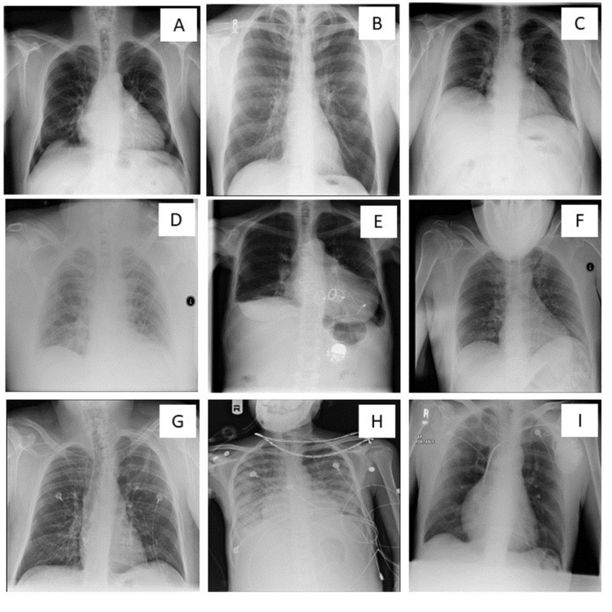
Optimal
- A: Optimal quality chest X-ray
Suboptimal (B–I)
- B: Non-inclusion of lung apices and costophrenic angles
- C: Low lung volume / inadequate inspiration
- D: Under-exposure
- E: Over-exposure
- F: Chin overlying the lung fields
- G: Patient rotation
- H: Foreign body (necklace) overlying the lung field
- I: Artifact obscuring part of the left costophrenic angle
Palpable surface parts used for centering the CR.

- A: Iliac Crest (ASIS)
- B: L5-S1 Joint Space
- C: SI Joints (Sacroiliac Joints)
- D: Ilium
- E: Sacrum
- F: Acetabulum
- G: Pubic Symphysis
- H: Greater Trochanter
- I: Pubic Ramus (Rami)
- J: Lesser Trochanter
Terminology Hub
Instant searchable index of core X-ray positioning terms, planar structures, and physics rules.
1. General Anatomical & X-Ray Positioning Terms
2. X-Ray Positioning Lines & Baselines
3. Specialized Anatomical Landmarks
4. Technical Imaging & Physics
5. Quality & Exposure Factors
6. Clinical & Pathological Indicators
7. Legal & Ethical Standards
Technical Reference Guide
Simple rules and setting baselines for setting up perfect x-ray exposures every time.
☢️ Comprehensive Technique Chart
Average (medium) adult profile baselines. Adjust up or down based on patient pathology and size.
- Skull AP 77 kVp @ 18 mAs
- Skull Lateral 73 kVp @ 15 mAs
- Waters 77 kVp @ 40 mAs
- Caldwell 72 kVp @ 32 mAs
- C-Spine AP/Obl/Odon 75 kVp @ 15 mAs
- C-Spine Lateral 80 kVp @ 30 mAs
- T-Spine AP/Obl 77 kVp @ 65 mAs
- T-Spine Lateral 60 kVp @ 120 mAs
- L-Spine AP/Obl 76 kVp @ 80 mAs
- L-Spine Lat/Spot 75 kVp @ 120 mAs
- Chest PA (72") 105 kVp @ 6 mAs
- Chest Lateral (72") 110 kVp @ 7.5 mAs
- KUB / Abdomen 70 kVp @ 55 mAs
- Ribs Upper 73 kVp @ 15 mAs
- Ribs Lower 72 kVp @ 55 mAs
- Shoulder 60 kVp @ 40 mAs
- Humerus 65 kVp @ 7.5 mAs
- Elbow 56 kVp @ 1.7 mAs
- Forearm 55 kVp @ 1.7 mAs
- Hand / Wrist 55 kVp @ 1.7 mAs
- Finger 52 kVp @ 1.7 mAs
- Pelvis 80 kVp @ 66 mAs
- Hip 77 kVp @ 65 mAs
- Femur 75 kVp @ 20 mAs
- Knee 55 kVp @ 7.5 mAs
- Tibia / Fibula 60 kVp @ 2 mAs
- Ankle / Foot 55 kVp @ 2 mAs
Think of kVp as your beam's punching power (penetration) and mAs as the total volume of x-rays. The 15% rule allows you to change the contrast (the shades of gray) of your image without changing the overall brightness.
| Desired Image Style | The 15% Adjustment | When & Why to Use It |
|---|---|---|
| Bold Black & White High Contrast / Short Scale |
↓ Turn kVp DOWN 15% ↑ Double mAs (x2) |
When: Extremities, ribs, and orthopedics. Why: Lowering the energy causes more x-rays to be completely absorbed by bone, leaving bright white bone against dark backgrounds for sharp structural borders. |
| Smooth & Detailed Grays Low Contrast / Long Scale |
↑ Turn kVp UP 15% ↓ Cut mAs in Half (-50%) |
When: Chest, abdomen, and soft tissue. Why: Higher energy easily punches through varying tissue densities, painting the plate with many subtle shades of gray to reveal delicate structures like lung markings. |
The technique chart assumes an average-sized adult. When your patient is significantly larger or smaller, use these simple mAs (x-ray amount) math tricks to keep your image quality perfect.
| Patient Size (Habitus) | The Adjustment Rule | Why It Works |
|---|---|---|
| Thin / Frail Asthenic / Hyposthenic |
Cut mAs in Half (-50%) | Less tissue to push through means you need fewer x-rays to reach the plate. |
| Average / Normal Sthenic |
Use Chart Baseline | Standard baseline settings are built specifically for this body type. |
| Large / Muscular Hypersthenic |
Double the mAs (x2) | Dense muscle and deep tissue absorb a lot of x-rays. You need twice as many to get a clear picture. |
Clinical Quiz
Test your knowledge of X-ray positioning, orientation, and exposure techniques.
Radiography Positioning And Exposure
You’ve put in the hard work and studied the materials—now let’s see how it all comes together. This quiz is designed to build your confidence and reinforce the key imaging principles you've learned. Take your time, focus on the details, and remember: precision in positioning is the key to diagnostic excellence.
About & Mission
The philosophy, scope, and purpose behind Radiography with Richie.
My name is Richie Shivers, RT(R)(CT)(ARRT). I am a registered radiologic technologist with experience in diagnostic radiography, computed tomography, and clinical radiology training. Over the course of my career, I have worked closely with imaging teams across the full spectrum of clinical care, from Level 1 Trauma Centers to specialized outpatient clinics.
Through that experience, I recognized a consistent opportunity to better support the field: Imaging team members are often tasked with performing high-quality radiography in high-pressure environments, where straightforward, practical, and accessible training resources are at a premium.
While formal academic programs provide the essential scientific foundation, many fast-paced clinical settings benefit from clear, safe, and foundational refreshers. There is a vital need for instruction that focuses on the practical “how-to” of x-ray positioning and the clinical “why” behind it—bridging the gap between complex theory and daily patient care.
That gap is why this site exists.
Radiography with Richie is an educational resource designed to support healthcare professionals in mastering the technical fundamentals of diagnostic x-ray positioning and patient safety. This program focuses on:
- Preparation
- Performance
- Perspective
- Presence
- Protocol
- Purpose
Every section is written in plain, clinical language, with step‑by‑step breakdowns that emphasize what to do, why it works, and how to avoid common mistakes.
This program is guided by a few core principles:
- Clarity over complexity
- Safety first, always
- Confidence is built through understanding, not memorization
- Good x-ray positioning prevents repeat exposure
Radiology should not feel mysterious or intimidating. When practitioners understand the reasoning behind x-ray positioning, they perform more confidently, patients feel more comfortable, and image quality improves.
This site is intended for multidisciplinary imaging teams, clinical support professionals, students learning basic imaging concepts, and frontline healthcare imaging providers.
The information presented is for educational and training support purposes only. It does not grant licensure or certification, replace employer training programs, or supersede facility protocols.
Always follow: Physician orders, facility policies, and applicable state laws and scope‑of‑practice requirements.
This program exists to make X‑ray education less intimidating, more accessible, clinically useful, and patient‑focused.
If this site helps even one member of the team feel more confident with x-ray positioning a patient safely and correctly, it has achieved its purpose.
— Stewart C. Bushong, ScD, Medical Physicist
Legal Disclaimer
Terms of Use and liability information.
By accessing and using Radiography With Richie (the “Site”), you acknowledge that you have read, understood, and agree to be bound by the following terms. If you do not agree with any part of this disclaimer, you should discontinue use of this Site immediately.
All content on Radiography With Richie — including but not limited to articles, videos, demonstrations, images, CGI visuals, x-ray positioning guides, and any other materials — is provided strictly for educational and informational purposes. This content does NOT constitute medical advice, clinical instruction, diagnostic guidance, or treatment recommendations. Nothing on this Site should be interpreted as a substitute for formal academic training, accredited clinical education, or direct supervision by a qualified healthcare professional. Users should not rely on this content to make clinical decisions or perform medical procedures.
Engaging with, completing, or reviewing any content on this Site does NOT confer, imply, or substitute for any professional licensure, certification, credential, continuing education credit, or clinical competency. This Site is not an accredited educational institution, certification body, or continuing education provider. Users must obtain and maintain all required professional credentials through the appropriate regulatory bodies and accredited programs in their jurisdiction. No representation is made that use of this Site satisfies any licensure, certification, or competency requirement.
Nothing on this Site constitutes the delegation, authorization, or assignment of clinical tasks, procedures, or responsibilities to any user. The site owner does not supervise, direct, or oversee any user’s clinical practice. Users must operate exclusively under the direct supervision and delegation authority of their own licensed supervising practitioner or employer, in accordance with applicable state and federal regulations. Any attempt to perform clinical procedures based solely on content from this Site is done entirely at the user’s own risk and responsibility.
All healthcare professionals, students, and trainees are individually and solely responsible for their own clinical decisions, actions, and conduct. Users must adhere to the scope of practice defined by their professional licensing board, their facility’s policies and procedures, and all applicable laws and regulations. The site owner assumes no liability for any clinical decisions, actions, or outcomes resulting from the use of information obtained from this Site. Professional judgment must always supersede any information presented here.
While reasonable efforts are made to provide accurate and current information, Radiography With Richie makes NO warranties, representations, or guarantees — express or implied — regarding the completeness, accuracy, reliability, suitability, or availability of any content on this Site. Medical imaging standards, techniques, protocols, and best practices evolve continuously. Users are responsible for verifying all information against current, peer-reviewed sources, manufacturer guidelines, and their facility’s approved protocols. The site owner shall not be held liable for any errors, omissions, or outdated information contained on this Site.
Any actions taken by a user based on content from this Site must be performed under the direct authorization of the user’s supervising provider, delegating authority, or employer. The site owner is NOT the user’s supervising provider, delegating authority, instructor, or employer, and accepts no responsibility or liability for any consequences — including but not limited to injury, disciplinary action, licensure issues, legal action, or adverse patient outcomes — arising from the application or misapplication of information obtained from this Site. Users assume full responsibility for how they utilize this content in any clinical or professional setting.
If you have any questions regarding this Legal Disclaimer, please contact us through the Radiography With Richie website.
Last Updated: April 2026
© 2026 Radiography With Richie. All rights reserved.
Privacy Policy
Transparency regarding how your information is collected, used, and protected.
Radiography With Richie (“we,” “us,” or “our”) respects your privacy and is committed to transparency about how information is collected, used, and protected when you visit our website (the “Site”). This Privacy Policy explains our practices. By using the Site, you agree to the terms described below.
Information You Provide: If you voluntarily submit information through contact forms, comments, email subscriptions, or any other interactive feature, we may collect your name, email address, and any other information you choose to provide. We do not require you to create an account to access educational content on this Site.
Information Collected Automatically: When you visit the Site, certain information may be collected automatically, including your IP address, browser type, operating system, referring URLs, pages viewed, time spent on pages, and the date and time of your visit. This information is collected through standard web server logs, cookies, and similar technologies.
We may use the information we collect to: respond to inquiries and communications you send us; deliver email updates or newsletters if you have opted in; improve the content, functionality, and user experience of the Site; monitor and analyze Site usage and trends; and comply with applicable legal obligations. We do NOT sell, rent, or trade your personal information to third parties for marketing purposes.
This Site may use cookies and similar tracking technologies to enhance your browsing experience, analyze traffic, and understand how visitors interact with the Site. Cookies are small data files stored on your device. You can control cookie preferences through your browser settings. Disabling cookies may affect certain features of the Site. Third-party services integrated with this Site (such as analytics providers or embedded content platforms) may also set their own cookies subject to their respective privacy policies.
This Site is hosted on WordPress and may use third-party tools and services including but not limited to analytics platforms (e.g., Google Analytics, Jetpack), embedded video platforms (e.g., YouTube), social media plugins, and email subscription services. These third-party services may collect information about your use of the Site in accordance with their own privacy policies. We encourage you to review the privacy policies of any third-party services you interact with through this Site. We are not responsible for the privacy practices of third-party services.
We do not sell your personal information. We may share your information only in the following limited circumstances: with service providers who assist in operating the Site (subject to confidentiality obligations); when required by law, regulation, legal process, or enforceable government request; to protect the rights, property, or safety of Radiography With Richie, our users, or the public; or with your explicit consent.
We take reasonable measures to protect the information collected through this Site from unauthorized access, alteration, disclosure, or destruction. However, no method of electronic transmission or storage is 100% secure. While we strive to protect your personal information, we cannot guarantee its absolute security. You use this Site and transmit information at your own risk.
This Site is not directed to children under the age of 13, and we do not knowingly collect personal information from children under 13. If we become aware that we have inadvertently collected personal information from a child under 13, we will take steps to delete that information promptly. If you believe a child has provided us with personal information, please contact us immediately.
Depending on your jurisdiction, you may have certain rights regarding your personal information, including the right to access, correct, delete, or restrict the processing of your data. If you have subscribed to email communications, you may opt out at any time by using the unsubscribe link provided in each email or by contacting us directly. To exercise any of your rights, please contact us using the information provided below.
This Site may contain links to external websites or resources that are not operated by us. We are not responsible for the content, privacy practices, or policies of any third-party websites. We encourage you to review the privacy policy of every site you visit. Inclusion of any link does not imply endorsement by Radiography With Richie.
We reserve the right to update or modify this Privacy Policy at any time. Any changes will be posted on this page with an updated “Last Updated” date. Your continued use of the Site after any changes constitutes your acceptance of the revised Privacy Policy. We encourage you to review this page periodically.
If you have any questions or concerns about this Privacy Policy, please contact us through the Radiography With Richie website.
Tools & Downloads
Helpful resources, guides, and PDF downloads for clinical practice.

ID Badge Technique Chart
A quick-reference technique chart designed to fit behind your clinical ID badge. Keep standard kVp and mAs settings easily accessible for quick adjustments on the floor.
Download PDF
X-Ray Positioning Flash Cards
Blank, structured flash cards with detailed sections for central ray placement, SID, patient x-ray positioning, and evaluation criteria. Print these out for active studying and clinical review.
Download PDF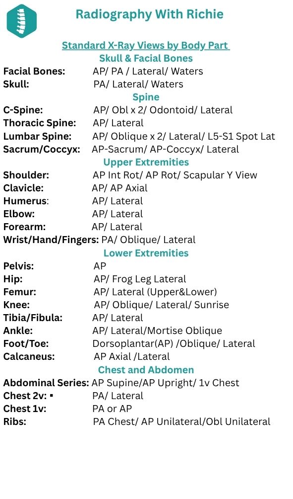
Standard Required Views
A quick-reference badge card outlining the standard required views for common diagnostic exams. Perfect for confirming baseline protocols before positioning the patient.
Download PDF
Image Critique Checklist
A rapid, 10-point self-evaluation checklist tailored for an ID badge. Run through these core criteria to verify x-ray positioning, collimation, and technique before sending an image to the provider.
Download PDFX-Ray Room Equipment
A detailed breakdown of the devices, components, and tools found in a clinical imaging room.